This highly detailed repair manual covers all repairs and servicing. All technical details taken directly from the manufacturer can be found in this manual, It is the factory manual from the manufacturer. Toyota 6BWC10, 6BWC15, 6BWC20, 6BWS11, 6BWS15, 6BWS20, 6BWR15 Electric Walkie High Lifter Truck service repair manual is the same manual used by professional technicians, mechanics and workshops around the world.
BoToyota 6BWC10, 6BWC15, 6BWC20, 6BWS11, 6BWS15, 6BWS20, 6BWR15 Electric Walkie High Lifter Truck cat service repair manual has easy to read text sections with top quality diagrams and instructions, will guide you through fundamentals of maintaining and repairing, step-by-step, to teach you what the factory trained technicians already know by heart. For that reason, you will not find it difficult to repair or to maintain some of the innovative features loaded on the vehicle when you have the manual. Using this repair manual is the true way to keep your vehicle working properly.
Effective Serial Number 6BWC10 – 20001 – UP
Models Covers:
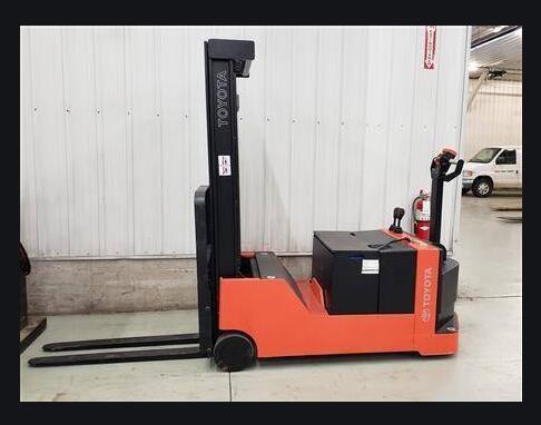
Toyota 6BWC10 Electric Walkie High Lifter Truck
Toyota 6BWC15 Electric Walkie High Lifter Truck
Toyota 6BWC20 Electric Walkie High Lifter Truck
Toyota 6BWS11 Electric Walkie High Lifter Truck
Toyota 6BWS15 Electric Walkie High Lifter Truck
Toyota 6BWS20 Electric Walkie High Lifter Truck
Toyota 6BWR15 Electric Walkie High Lifter Truck
Manual Covers:
Standard Codes
Warning Symbols
Warning Levels
Prohibitory Symbols
Ordinance Symbols
Safety
General Safety
Battery Safety
Static Safety
Welding Safety
Introduction, Service Manual
Contents, Section M
Machine Information
General Product Information
Presentation of Walkie Trucks
Truck Side Views
Intended Truck Application
Prohibited Truck Application
Truck Data
6BWC10 Dimensions
6BWC15 Dimensions
6BWC20 Dimensions
6BWS11 Dimensions
6BWS15 Dimensions
6BWS20 Dimensions
6BWR15 Dimensions
Data Plate
Main Components
Inch (SAE) and Metric Fasteners
Introduction
Nomenclature, Threads
Strength Identification
Conversion of Metric and English Units
Technical Service Data
Ordering Spare Parts
Contents, Section P
Planned Maintenance
Introduction, Maintenance
Jacking Truck Off The Floor
Elevate Rear of Truck
Elevate Either Side of Truck
Lubricants
Standard
Corrosion
Cold Storage
Service Schedule
Planned Maintenance Schedule
Planned Maintenance Procedures
Services Performed Daily or Every 8 Operating Hours
Services Performed Monthly or Every 120 Operating Hours
Services Performed Every 480 or 960 Operating Hours
Services Performed Annually or Every 1400 Operating Hours
Lubrication Chart
Oil and Grease Specifications
Approved Oils and Grease
6BWC Grease & Mast Adjustment Points Location
6BWS Grease & Mast Adjustment Points Location
6BWR Grease & Mast Adjustment Points Location
Contents, Section S
Service Instructions
Frame/Chassis
General
Main Components
Inspection Covers
Battery Roller (Optional)
Battery Cover, Optional (6BWS11 EE Trucks Only)
Inspection
Removal
Installation
Battery Rollers
Inspection
Replacement
Driver Controls, One Spool
Removal
Installation
Driver Controls, Two Spool
Removal
Installation
Decals
Decal with Protective Sheet
Decal without Protective Sheet
Motor Maintenance
Schedule/Troubleshooting
General Information
Operating Conditions
Troubleshooting
Motor Repair
Pump Motor
Pump Motor Removal
Pump Motor Installation
Drive Motor
Brush Replacement
Drive Motor Removal
Drive Motor Installation
Component Repair
Disassembly
Inspection
Drive End head
Commutator End Head
Bearings
Brush and Commutator
Armature
Frame and Field Assembly
Assembly/Testing
Transmission
System Description
Troubleshooting
Kick Panel
Transmission Repair
Removal
Installation
Transmission Assembly
Disassembly
Assembly
Axle Seal
Removal
Installation
Parking Brake System
Brake Theory of Operation
Brake Adjustment
Brake Shoe Removal / Installation
Drive Wheel
Removal
Installation
Tire Pressing Procedure
Support/Swivel Wheel
Maintenance and Adjustments
Caster Adjustment
Troubleshooting
Stabilizing Caster
Load Wheels
Removal and Installation
Caster Assembly
Disassembly
Inspection
Assembly
Installation
Steering Arm/Wheel, Tiller Arm
Removal
Inspection
Installation
Steering Arm/Wheel, Head
Control Handle Head
Removal
Installation
Direction Control Switches
Raise, Lower, and Horn Switches
Potentiometer
Removal
Installation
Reverser Assembly Replacement
Electrical Functions
General
Adjustable Settings
References
Key Switch S17 in ON Position
Operating Arm in Drive Position, S10, Brake Switch Closed
Travel Request, Forks First
Travel Request, Forks Trailing
Reversing/Motor Brake Forks First to Forks Trailing Direction
Reversing/Motor Brake Forks Trailing to Forks First Direction
Reverser switch
Lifting Forks
Lowering Forks
Horn
Options
Lifting Forks (Manual Valve)
Tilting Forks
Side Shifting Forks
Extend/Retract Forks
Electrical Symbols
Electrical Schematics
Battery
Removal
Installation
Battery Maintenance
Battery Inspection and Care
Battery Exterior Cleaning
Charging
Storage
Battery History Record
Battery Connector
Location
Inspection
Installation
200 Amp System Line Contactor
Replacement
Removal
Installation
300 Amp System Line Contactor (6BWC15/20 only)
Maintenance
Removal/Replacement of Contact Tips
200/300 Amp System EE Line Contactor
Maintenance
Removal/Replacement of Contact Tips
Battery Controller/Hourmeter/Lift Interrupt
General Information
Electrical
Voltage
Battery Controller (BC)
General Information
Reset
Key Switch
Hourmeter
Troubleshooting
Battery Discharge Indicator (BDI)
Hourmeter
Start/Stop Switches
General
Test/Inspection
Master Control On/Off Switch (S21)
Inspection
Removal
Installation
Light Assemblies
Warning Lights (Option)
Removal
Installation
Travel/Back-up Alarm (Option)
Removal
Installation
Transistor Controller
Basics Of Circuit Operation
Control Features
Maintenance
Safety
Cleaning
Motor Circuit
Control Circuit
Troubleshooting Guidelines
General
Shorts to Frame Test
Definitions
Diagnostics and Troubleshooting
Handset Diagnostics
Troubleshooting
Troubleshooting Chart
Technical Specification
Troubleshooting Chart Using Handset
Transistor Controller Troubleshooting
Troubleshooting Chart Index
Troubleshooting Charts
Hydraulic System
General
Description of Function
Main Components
Lift (Solenoid valve)
Lift (Mechanical Valve)
Lower (Solenoid Valve)
Lower (Mechanical Valve)
Relief Pressure
Compensating Cylinder
Reach (Solenoid valve)
Tilt (Solenoid valve)
Sideshift (Solenoid valve)
Maintenance
Adjustments
Troubleshooting
Primary Malfunctions
Definitions
Removal
Installation
Hydraulic Schematics
Hydraulic Fluid
Hydraulic Fluid Selection
Changing Hydraulic System Fluid
System Draining
Refilling System
Bleeding Hydraulic System
Hydraulic Tank
Removal
Installation
Hydraulic Pump Assembly
Disassembly
Inspection
Assembly
One Spool Control Valve
Operators Controls Removal
Control Valve Disassembly and Inspection
Operators Controls Installation
Two Spool Control Valve
Operators Controls Removal
Control Valve Disassembly and Inspection
Operators Controls Installation
Lift Cylinder, Two Stage Mast
Removal
Disassembly
Assembly
Installation
Two Stage Full Freelift Mast Cylinder Repair
Removal
Disassembly
Assembly
Installation
Two Stage Full Freelift Mast Staging Cylinder Repair
Removal
Disassembly
Assembly
Installation
Lift Cylinder, Three Stage Mast
Repair
Removal
Disassembly
Assembly
Installation
Reach Cylinder, 6BWR15
Removal
Disassembly
Inspection
Assembly
Installation
Tilt Cylinder
Removal
Disassembly
Inspection
Assembly
Installation
Removal
Disassembly
Inspection
Assembly
Installation
Shimming Carriage with Mast on Truck
Repair
Removal
Disassembly
Assembly
Installation
Lift Chain
Lift Chain Adjustment:
Lift Chain Maintenance
Lift Chain Inspection
Lift Chain Replacement
Mast, Three Stage
Shimming Carriage with Mast on Truck
Repair
Removal
Disassembly
Assembly
Installation
Lift Chain
Sideshifter
Mounting Instructions
Installation
Operation
Maintenance
Carriage Removal
Upper Pad Replacement
Lower Pad Replacement
Cylinder
Troubleshooting
No Sideshifting
Very Slow Sideshifting
Irregular Sideshifting
Single Reach, 6BWR
Maintenance
Inspection
Adjustment
Repair
Disassembly
Assembly
Carriage Bumpers
Reach Adjustment
Fork Carriage Pivot Pins
Carriage Roller Bearings
Removal
Installation
Removal
Inspection
Installation
Load Backrest
Removal
Installation
Handset Operation
Operating Modes
Revert to Previous Settings
Handset Self Test
Electrical Controllers (Handset)
Display Screen
Menu Navigation Key
Data Inc/Dec Key
Bookmark Keys
Operation
Menu Structure
Main Menu
Interface Protocols and Backward Compatibility
Parameter Changing
Real-Time Monitoring
Reading Faults and Diagnostic History File
Cloning and Restoring the Previous Programming
Information Displays
Programmer SetUp
More Theres——–
============
**Total Pages: 468
**File Format: PDF
**Language: English
**Requirements: Adobe PDF Reader & WinZip
**Compatible: All Versions of Windows & Mac, Linux OS, Iphone, Ipad, Android etc…
After your payment, you will have instant access to your download. We will always try to get the full satisfaction of our customers. Even after you have purchased this manual, we will pay full attention to any issues, regardless of the nature of the situation.
THE DOWNLOAD LINK WILL ALSO BE SENT TO YOUR E-MAIL.
So please make sure your email address is correct. Don’t Forget to Check Spam / Junk if can’t find the new message in your email inbox immediately.
Thanks for visiting!
Any questions please contact: admin@servicemanualperfect.com