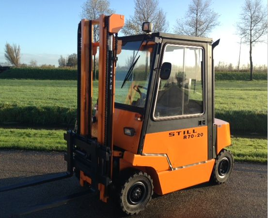
This highly detailed repair manual covers all repairs and servicing. All technical details taken directly from the manufacturer can be found in this manual, It is the factory manual from the manufacturer. Still R70-20 bis 45 Series R7012, R7013, R7015, R7016, R7023, R7024, R7041, R7042, R7043 Fork Truck service repair manual is the same manual used by professional technicians, mechanics and workshops around the world.
Still R70-20 bis 45 Series R7012, R7013, R7015, R7016, R7023, R7024, R7041, R7042, R7043 Fork Truck service repair manual has easy to read text sections with top quality diagrams and instructions, will guide you through fundamentals of maintaining and repairing, step-by-step, to teach you what the factory trained technicians already know by heart. For that reason, you will not find it difficult to repair or to maintain some of the innovative features loaded on the vehicle when you have the manual. Using this repair manual is the true way to keep your vehicle working properly.
Models Covers:
R7012
R7013
R7015
R7016
R7023
R7024
R7041
R7042
R7043
Manual Covers:
01. Chassis Frame and Counterweight
02. Steer Axle
Technical Data for Maintenance Service
Steer Axle – Construction
Steer Axle removal & installation
Wheel Hub – Removal & Dismantling
Wheel Hub – Reassembling and Installation
Checking the steering angles
Wheel angle stop adjustment
Stub axle removal and installation
Track rod and steer cylinder bearing at stub axle
Track rod bearing on steering bell crank
Steer cylinder mounting at axle beam
Bell crank mounting
03. Power Axle
Technical Data for Maintenance service
Power Axle / Description
Spur-type reduction gearbox / Sectional view
Power axle removal and installation
Wheel hub removal and installation
Half -shaft removal and installation
04. Wheels and Tyres
06. Steering
Technical Data for Maintenance Service
Steering – Operation
Steering unit removal
Steering unit installation
Checking the hydraulic oil pressure
Steer cylinder – Dismantling
Steer cylinder – Reassembling
Priority valve
Repairing or cleaning the priority valve
07. Hydraulic-Servo-Brake
Technical Data for Maintenance Service
Mechanical configuration
Operation of automatic adjuster
Brake shoe replacement and basic adjustment
Turning out the inside diameter of the brake drums
on a lathe in the event of wear
Master cylinder
Parkingbrake adjustment
08. Electrical Installation
Technical Data for Maintenance Service
Mechanical configuration of electrical installation
General description, Method of operation
Testing the insulation resistance (earthing)
Driving controls
– Keyswitch
– Directional control switch
– Electronic start delay unit
– Instrument panel
– Warning horn / Horn button
-Travel sender unit
– Foot brake switch / Parking brake switch
Tachogenerator
Current sensor
Speed (rpm) sensor
Alternator
Starter batteries
Truck wiring
Fuses
Contactor panel assembly
– Contactor
-Relays
– Logic card ‘drive control’
– Power board (or unit)
Pc.b. ‘servomotor’
Servomotor injection pump
Angle of rotation sensor, hydraulics
10. Hydraulic System
Technical Data for Maintenance Service
Operation of Lift and Tilt Hydraulics
Directional Contol Valve block complete
with operating levers
Directional Control Valve block
Directional Control Valve block
Directional Control Valve block
Directional Control Valve
Directional Control Valve
Directional Control Valve
Directional Control Valve block
Directional Control Valve block
Anti-cavitation Valve
Hydraulic Pump
Hydraulic Pump Drive
Hydraulic Tank
Hydraulic Tank
Return Line Filter
Hydraulic fittings & unions
Speeds
Hydraulic Circuit Diagram
11. Drive Motor
Technical Data for Maintenance Service
Drive-motor
Drive motor, construction
Wiring diagram
Neutral plane or zone
Posisiton of motor terminals
Inspecting and changing the motor brushes
Brush spring tension
Drive motor removal
Drive motor installation
Drive motor – Dismantling
Drive motor reassembly
Generator
Generator, type
Wiring diagram
Neutral plane or zone
Position of generator terminals
Inspecting and changing the carbon brushes
Brush spring tension
Generator removal
Generator installation
Generator- Dismantling
Generator reassembly
External fan cooling
Description
Fan removal
Fan installation
Adjusting V-belt tension
Replacing the V-belt
Clean air filter
Fan – Dismantling
Fan – Reassembling
Thermal monitoring
Thermal switch in drive motor
Operation of the thermal switch
Checking the thermal switch
Checking temperature warni ng light as well as the leads
in the truck
Changing the thermal switch
General hints
Insulation resistance
Measuring insulation resistance
Turning down the commutator a lathe
Minimum permissible commutator diameter
Undercutting the mica
13. Pressure Regulator Unit I and II
Pressure Regulator Unit I and II – Operation
Pressure Regulator Unit
Pressure limiting valve
Pressure gauge
Directional control valve block
Fitting restrictors
Pressure limiting for sideshift clamps
15. Diesel Engine- relating to Mercedes-Benz Diesel engine
Technical Data
Diesel engine removal and installation
Cooling fan
Fuel system
Exhaust gas system
Air filtering system
Diesel generator set/Lubrication system
Diesel generator set/Cooling system
Excerpt from the original MB Workshop manual covering engine model OM 601
Contents relating to MB engine
Section view MB – OM 601
Testing compression pressure
Remilling prechamber sealing surface
Removing, installing prechambers
Removing, installing cylinder head
Removing and installing vibration damper and hub
Renewing front crankshaft radial seal
Testing timing of camshaft
Removing and installing camshaft
Renewing timing chain
Removing, installing chain tensioner
Removing, installing tensioning rail
Removing, installing injection nozzles
Setting start of delivery (after testing)
Removing, installing injection pump
Removing, installing V-belt
Removing, installing V-belt tensioning device
Removing, installing coolant pump
Removing, installing thermostat
20. Elevating mast
Technical Data for Maintenance Service
Mast types / Removal of mast
Telescopic mast
Hi-Lo mast
Triple mast
Carriage stops
Support rollers
Guide rollers
Hoist cylinders
Lowering valve
Line failure safety device
22. Fork carriage
23. Fork arm
24. Mast pivots
25. Tilt cylinder
S-D. Diagnostic instructions
More Theres——–
============
** Total Pages: 307
** File Format: PDF
** Language: English
** Requirements: Adobe PDF Reader & WinZip
** Compatible: All Versions of Windows & Mac, Linux OS, Iphone, Ipad, Android etc…
NO waiting! You will have instant access to your download! All pages are printable, No shipping fee, No waiting nervously for the postal delivery, you can start doing your repairs right away!
We will always try to get the full satisfaction of our customers. Even after you have purchased this manual, we will pay full attention to any issues, regardless of the nature of the situation.
THE DOWNLOAD LINK WILL ALSO BE SENT TO YOUR E-MAIL.
So please make sure your email address is correct. Don’t Forget to Check Spam / Junk if can’t find the new message in your email inbox immediately.
Any questions please contact: admin@servicemanualperfect.com
Thanks for visiting!